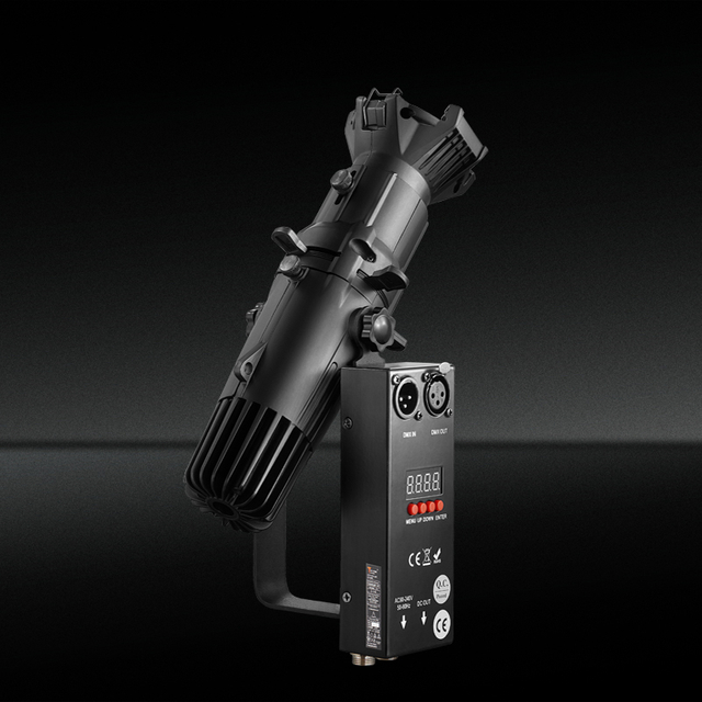
What Beam Angle Options Are Available for a Mini LED Profile Spotlight?
Views: 0 Author: Site Editor Publish Time: 2026-08-28 Origin: Site


Specifying a Mini LED Profile Spotlight with an incorrect beam angle results in light spill, inadequate target illumination, visual glare, and compromised spatial aesthetics. In compact form factors, the margin for optical error is virtually zero. You cannot fix a bad beam angle with dimming or physical baffles without ruining the fixture's output. This guide breaks down the technical evaluation of beam angle options—ranging from ultra-narrow fixed spots to variable optics. We provide a framework to match lens specifications with specific throw distances, subject sizes, and environmental constraints. You will learn how to calculate beam diameters, evaluate the trade-offs between fixed and adjustable lenses, and mitigate common installation risks associated with ultra-miniature lighting fixtures. We focus on field-tested metrics, bypassing marketing claims to look directly at photometric performance and mechanical reliability.
- Precision is Application-Dependent: Narrow beam angles (5°–15°) are mandatory for high-contrast, long-throw highlighting, while wider angles (38°+) serve ambient and wash requirements.
- Fixed vs. Variable Optics: An Adjustable Beam Spotlight offers operational flexibility for dynamic spaces (like galleries), but fixed lenses typically deliver higher optical efficiency and sharper framing.
- Spacing Requires Calculation: Recessed or track placement must account for the beam diameter at the target distance, not just the physical distance between fixtures.
- System Compatibility: The chosen beam angle must align with the fixture’s framing shutters, gobo capabilities, and thermal management limits to ensure long-term reliability.
The Role of Beam Angles in a Mini LED Profile Spotlight
Defining what constitutes a successful lighting installation requires looking beyond simple brightness. A successful deployment achieves high center beam intensity, zero spill outside the framed area, and a completely uniform field. Achieving these metrics relies entirely on selecting the correct beam angle for the specific architectural context. When light escapes the intended target zone, it degrades visual contrast. This becomes highly visible in museums, galleries, and high-end retail spaces where the illuminated object must stand out against a darker background.
Beam Angle vs. Field Angle
Lighting professionals must distinguish between beam angle and field angle to accurately predict how light behaves in a physical space. The beam angle represents the central cone of light where the intensity drops to 50% of the maximum center beam candlepower (CBCP). Most manufacturers use this measurement to categorize their lenses. However, relying solely on the beam angle leads to poor installation outcomes.
The field angle measures the wider cone where light intensity drops to 10% of the maximum center intensity. Evaluating both metrics is mandatory for predicting light spill in tight architectural spaces. A fixture might boast a tight 15-degree beam angle but suffer from a wide 35-degree field angle. That discrepancy means stray light will wash over adjacent walls, display cases, or artwork. High-quality optical systems minimize the gap between the beam and field angles, resulting in a sharp, defined edge with minimal haloing.
Beam vs. Field Angle Impact
| Metric | Intensity Threshold | Visual Impact on Target | Design Implication |
|---|---|---|---|
| Beam Angle | 50% of CBCP | Determines the primary punch and core illumination area. | Used to calculate the main target coverage and required lumen output. |
| Field Angle | 10% of CBCP | Determines the soft edge and potential light spill. | Used to calculate spacing to avoid overlapping shadows or glare on adjacent surfaces. |
Form Factor Constraints
Ultra-miniature housings, such as 4cm profiles, severely limit the physical size of the internal lens and reflector. Physics dictates that controlling light requires space. A larger reflector can gather and direct photons more efficiently than a microscopic one. Engineering a micro-profile fixture involves significant trade-offs between maintaining a tiny footprint and achieving a clean, artifact-free beam spread.
In these compact designs, the LED chip sits extremely close to the primary optic. This proximity makes it difficult to collimate the light rays perfectly. Manufacturers must use highly precise aspheric lenses or complex total internal reflection (TIR) optics to shape the beam. Any microscopic flaw in the lens manufacturing process translates into visible artifacts, color fringing, or uneven illumination on the target surface. Specifiers must recognize that miniaturization inherently complicates optical control. You cannot expect a 2-inch fixture to have the exact same optical forgiveness as an 8-inch theatrical ellipsoidal.
Standard Fixed Beam Angle Categories and Applications
Miniature profile fixtures typically utilize standard fixed lens categories. Breaking down these industry-standard options helps specifiers match the optical tool to the specific architectural task. Each category serves a distinct purpose based on its light distribution characteristics.
Standard Fixed Lens Summary
| Beam Category | Angle Range | Key Characteristic | Primary Application |
|---|---|---|---|
| Narrow Spot | 5°–15° | High CBCP, sharp cutoff | Long-throw highlighting, small objects |
| Medium Flood | 20°–35° | Balanced intensity | General accent, larger artwork |
| Wide Flood | 38°–60°+ | Diffused footprint | Ambient lighting, wall washing |
Narrow Spot (5°–15°)
Narrow spot lenses deliver high Center Beam Candlepower (CBCP) and a very sharp cutoff. These lenses concentrate the LED output into a tight, intense column of light. They are ideal for highlighting small objects, such as jewelry or delicate artifacts, where precision is paramount. When you need to illuminate a 6-inch sculpture from a 15-foot ceiling, a 10-degree lens is the only viable option.
These angles excel in long-throw applications. They create a high-contrast spotlight effect ideal for isolating a standard-sized painting or solo display element without illuminating the surrounding wall. When mounted on high ceilings, a narrow spot ensures sufficient light reaches the target area without scattering. However, the intense concentration of light means any misalignment during installation is immediately noticeable. A fraction of an inch of movement at the fixture translates to several inches of deviation at the target.
Medium Flood (20°–35°)
Medium flood lenses offer a balance between central intensity and broader coverage. They do not punch through space as aggressively as narrow spots, nor do they wash out like wide floods. This balanced distribution makes them the workhorse of architectural accent lighting. Most standard gallery installations rely heavily on this range.
Ideal use cases include illuminating larger artwork, retail displays, and mannequins where subjects require broader, yet controlled, illumination. A 25-degree lens can cover a medium-sized sculpture evenly from a standard track height. It provides enough punch to create visual hierarchy in a room without creating harsh, theatrical shadows. Field engineers often default to 24-degree or 36-degree lenses when the exact target size is unknown during the rough-in phase.
Wide Flood (38°–60°+)
Wide flood lenses produce a diffused intensity and a wide footprint. They scatter light over a large surface area, drastically reducing the center beam intensity. These lenses are rarely used for pinpoint accenting. Instead, they serve ambient lighting, wall washing, and applications requiring overlapping beams to eliminate shadows in small spaces.
For ambient wall-wash applications, placement metrics are strict. A 38-degree beam is typically paired with a specific wall offset. Placing recessed fixtures 18 to 22 inches from the back wall ensures smooth, scallop-free coverage. If placed too close to the wall, the wide beam creates harsh parabolic shapes near the ceiling line. Proper spacing and offset calculations are mandatory when deploying wide flood optics.
Steps for configuring a wide flood wall wash:
- Measure the total ceiling height to determine the required throw distance to the floor.
- Calculate the 30% overlap distance based on the beam diameter at eye level.
- Set the track or recessed housing exactly 18 to 24 inches away from the vertical surface.
- Aim the fixtures at a 20-degree tilt toward the wall to push the peak candela down the surface.
- Lock the pan and tilt mechanisms tightly to prevent drifting over time.
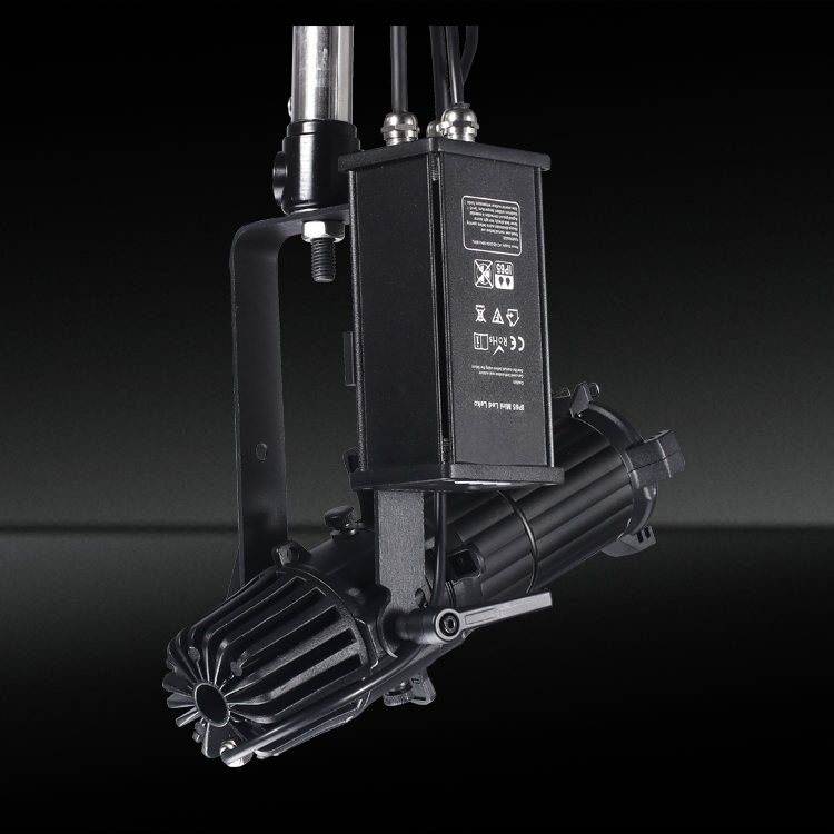
Fixed Lenses vs. an Adjustable Beam Spotlight
Lighting designers frequently face a choice between static and variable lens systems. Evaluating the operational and optical differences between these two approaches dictates the long-term success of the lighting installation. Each system carries specific mechanical and photometric trade-offs that impact maintenance schedules and visual quality.
Optical Efficiency and Precision
Fixed lenses generally offer higher light transmission. A single piece of precisely molded glass or optical-grade polycarbonate introduces fewer barriers to the light path. Every time light passes through a glass surface, approximately 4% of the output is lost to reflection unless expensive anti-reflective coatings are applied. Fewer optical elements mean less light is lost to internal reflection or absorption. This results in higher overall lumen output and sharper gobo or framing shutter projection.
Variable systems require multiple moving lenses to change the focal length and beam spread. Lower-tier adjustable lenses often suffer from chromatic aberration or edge-blurring. As the lenses move apart, different wavelengths of light refract at slightly different angles, causing color fringing at the edge of the beam. Fixed lenses, optimized for a single focal point, largely eliminate this optical distortion. If you need razor-sharp shutter cuts on a painting, a fixed lens will always outperform a variable lens of the same price tier.
Flexibility for Dynamic Environments
Despite the slight drop in absolute optical efficiency, an Adjustable Beam Spotlight provides massive operational flexibility. Multi-use spaces, such as museums with rotating exhibits or retail stores with seasonal displays, see target sizes and throw distances change frequently. A fixed system requires technicians to climb ladders, open fixtures, and physically swap lenses to accommodate new displays.
The return on investment for variable optics becomes clear when calculating labor savings. Adjusting a single fixture via a manual zoom barrel or motorized control takes seconds. This flexibility allows curators and visual merchandisers to fine-tune the lighting design on the fly, ensuring perfect coverage regardless of the exhibit's physical dimensions. You eliminate the need to store boxes of spare lenses in a back room.
Mechanical Reliability
Variable optics introduce moving parts into miniature fixtures. Assess the long-term durability of the zoom mechanics before specification. Two primary mechanisms exist: helicoid threads and push-pull barrels. Helicoid systems use a threaded barrel that rotates to move the lenses closer or further apart. This provides smooth, granular control and generally resists slipping.
Push-pull systems slide back and forth on internal rails. While faster to adjust, they can degrade over time. Miniature fixtures are frequently exposed to heat from the LED and ambient dust. Dust ingress can foul the sliding mechanisms, making them stiff or causing them to bind. When specifying adjustable fixtures for long-term commercial use, verify the IP rating and the quality of the mechanical lubricants used in the zoom assembly.
Zoom Mechanism Comparison
| Mechanism Type | Adjustment Speed | Precision Level | Vulnerability to Dust/Heat |
|---|---|---|---|
| Helicoid Thread | Slower (requires rotation) | Very High | Low (threads block debris) |
| Push-Pull Barrel | Fast (linear slide) | Moderate | High (rails can bind) |
Technical Evaluation Criteria for Lens Selection
Selecting the correct lens requires cross-referencing beam angle options with other critical lighting metrics. You cannot choose a beam angle in isolation. It must integrate seamlessly with throw distance, shutter capabilities, and color temperature requirements.
Throw Distance and CBCP Calculations
Throw distance dictates the required Center Beam Candlepower. The inverse-square law governs this relationship. The law states that the intensity of light is inversely proportional to the square of the distance from the source. If you double the throw distance, the illuminance on the target drops to one-quarter of its original value. You must account for this physics principle when selecting a lens.
A wider beam angle requires significantly higher lumen output to maintain the same illuminance at a given distance. Because the wide lens spreads the light energy over a geometrically larger area, the center punch drops dramatically. When calculating requirements, always use the manufacturer's IES files to determine the exact CBCP at your specific mounting height. Do not rely solely on total lumen output, as a 1000-lumen fixture with a 60-degree beam will appear drastically dimmer on a target than a 1000-lumen fixture with a 10-degree beam.
Integration with Framing Shutters and Gobos
Profile spotlights often feature internal framing shutters or gobo slots. The chosen beam angle dictates the maximum size and sharpness of a projected gobo or framed polygon. Narrow lenses project smaller, sharper images over long distances. Wide lenses project larger images but struggle to maintain edge sharpness due to the extreme refraction angles required.
Evaluate the risk of halo effects when using wide-angle lenses with internal shutters. If the shutter blades sit too far from the focal plane of the wide lens, they will not cut the light cleanly. Instead, they create a blurry, glowing edge around the framed area. If crisp geometric framing is the primary goal, specify narrower beam angles or fixtures explicitly engineered with complex multi-lens condenser systems.
Color Temperature (CCT) and Beam Uniformity
Different lenses interact uniquely with the full range of LED options found in ultra-mini fixtures. These fixtures often support static white, static color, RGB, RGBW, or dynamic white arrays. Matching the Correlated Color Temperature (CCT) to the environment is standard practice. For example, 3000K works well for warm gallery settings, while 4000K or 5000K suits crisp retail displays.
However, a narrow beam at cooler temperatures can appear overly harsh and clinical if not properly framed. Furthermore, multi-die arrays present a specific challenge for lenses. Because the red, green, blue, and white chips sit in slightly different physical locations on the circuit board, a simple lens will project those colors at slightly different angles. This causes color separation or color fringing at the edges of the beam. High-quality fixtures use specialized homogenizing lenses or mixing rods before the primary optic to blend the colors thoroughly before shaping the beam.
Implementation Realities: Spacing, Placement, and Risks
Theoretical optical performance means nothing if the practical installation is flawed. Practical considerations for installation and commissioning dictate the final visual outcome. Spacing, overlap, and thermal management require strict attention during the design phase.
Calculating Beam Diameter at Distance
Never guess the light spread. Calculate it. The standard formula for determining the physical size of the light pool is straightforward: Beam Diameter = Angle Multiplier × Throw Distance. The angle multiplier is a mathematical constant derived from the beam angle. If the throw distance is 10 feet, and you use a 20-degree lens (multiplier 0.35), the beam diameter is 3.5 feet.
Common Beam Angle Multipliers
| Beam Angle | Multiplier | Diameter at 10ft Throw |
|---|---|---|
| 10° | 0.18 | 1.8 feet |
| 20° | 0.35 | 3.5 feet |
| 30° | 0.54 | 5.4 feet |
| 40° | 0.73 | 7.3 feet |
While the formula provides a quick estimate, using photometric data is mandatory for professional applications. Import these files into lighting design software to map the exact light distribution before procurement. This process reveals the field angle drop-off and helps identify potential light spill onto adjacent surfaces.
Overcoming Spacing and Overlap Challenges
A common industry misconception states that narrow beam fixtures automatically require closer physical spacing than wide beams. This is false. Spacing is dictated by the intersection of beam diameter, ceiling height, and desired overlap, not just the lens angle. You might space narrow fixtures far apart if the goal is isolated, high-contrast spotlighting on individual pedestals.
For ambient lighting, calculate overlap carefully. If you want uniform wall washing, the beam diameters must overlap by approximately 30% to 50% at the target surface. If using 38-degree lenses, calculate the beam diameter at the floor or eye level, then space the fixtures so their light pools intersect appropriately. Failure to calculate this overlap results in dark spots and uneven illumination across the space.
Thermal Management in Ultra-Mini Fixtures
The internal optics and beam shaping tools, such as shutters or irises, impact the thermal load of the fixture. When you close framing shutters to create a tight square, you block light energy. That blocked light energy converts directly into heat inside the fixture housing. In an ultra-miniature 4cm profile, this trapped heat has very little surface area to escape.
The primary mitigation strategy involves specifying fixtures with adequate heat sinking. The aluminum body must possess enough mass and surface area to dissipate the heat efficiently. Excessive internal temperatures cause LED phosphor degradation, resulting in color shifts and premature lumen depreciation. Regardless of the lens attached, verify the thermal testing data provided by the manufacturer to ensure the fixture can survive continuous operation in enclosed architectural spaces.
Conclusion
The optimal beam angle is a specific mathematical relationship between the fixture's placement, the subject's size, and the desired visual contrast. Selecting the right optic requires balancing optical efficiency against operational flexibility, all while managing the physical constraints of miniature housings.
- Request IES files from the manufacturer and import them into DIALux to verify field angle drop-off.
- Calculate the exact beam diameter at your specific throw distance before finalizing the fixture layout.
- Order a physical sample to test framing shutter sharpness and mechanical zoom durability on site.
- Measure the ambient room temperature at the installation height to confirm the fixture's thermal management limits.
FAQ
Q: How do I calculate the beam spread for a specific throw distance?
A: Multiply the throw distance by the angle multiplier of your specific lens. For example, a 30-degree beam has a multiplier of roughly 0.54. At a 10-foot throw distance, the beam diameter will be 5.4 feet. For precise measurements, always use the manufacturer's IES photometric files in lighting software.
Q: Can I change the beam angle on a fixed Mini LED Profile Spotlight after installation?
A: Yes, but it requires physical labor. You must access the fixture, open the optical barrel, and physically swap the fixed lens for one with a different degree. This is time-consuming compared to using a variable zoom fixture, which adjusts via a mechanical barrel.
Q: What is the difference between beam angle and field angle in profile spotlights?
A: The beam angle is the central cone of light where intensity is at least 50% of the maximum center brightness. The field angle is the wider outer cone where intensity drops to 10%. Field angle determines how much stray light or spill will hit surrounding areas.
Q: Why does a narrow beam angle require different fixture spacing than a wide beam?
A: Spacing depends on the required overlap at the target surface. A narrow beam creates a smaller diameter pool of light. If uniform ambient coverage is the goal, narrow fixtures must be placed closer together. If isolation is the goal, they can be spaced further apart.
Q: Is an adjustable beam spotlight as bright as a fixed lens spotlight?
A: Generally, no. Adjustable systems use multiple moving lenses, which slightly reduces optical transmission due to internal reflections and light absorption. Fixed lenses use fewer optical elements, resulting in slightly higher overall lumen output and sharper projection edges.
Q: How do framing shutters affect the effective beam angle of a mini spotlight?
A: Framing shutters physically block portions of the light beam to create geometric shapes. While they do not change the optical properties of the lens itself, they reduce the effective spread and total lumen output hitting the target by cutting off the outer edges of the beam.